
A practical guide for engineers, plant operators, and procurement teams selecting the right impeller pump for real operating conditions.
|
What Is an Impeller Pump The Anatomy of an Impeller PumpHow Do Impeller Pumps Work Key Types of Pump Impellers Key Applications of Impeller Pumps Advantages of Impeller Pumps Impeller Diameter in Centrifugal Pumps Key Considerations for Pump Impeller Selection |
How Impeller Pumps Compare to Gear Pumps How to Choose the Right Impeller Type for Your Industry Maintenance and Troubleshooting Common Impeller Pump Issues and Solutions Frequently Asked Questions About Pump Impellers Looking for a Trusted Industrial Pump Manufacturer Conclusion
|
If you have ever stood next to a running centrifugal pump and wondered what is actually happening inside the casing, the answer almost always comes back to one part: the impeller. Whatever fluid you are moving — clean water, wastewater, mud, or a corrosive process chemical — the impeller pump is the workhorse behind it, and the impeller itself is the single component that decides how much flow and pressure you actually get out of the machine.
This guide walks you through how an impeller pump works, the main impeller types you will encounter on a project, and how to match impeller design and material to your fluid, your solids content, your temperature, and your application. Along the way you will find real performance figures, a comparison table against gear pumps, and a maintenance and troubleshooting checklist you can hand to your operations team. By the end, you should be able to look at a pump datasheet and understand exactly why the impeller was specified the way it was.
An impeller pump is any pump that moves fluid using a rotating component called the impeller, which imparts kinetic energy to the liquid through centrifugal force or, in some designs, through the flexing action of soft rubber vanes. In technical terms, the impeller converts the mechanical energy delivered by a motor shaft into fluid velocity, and the pump casing then converts part of that velocity into usable pressure, or head.
Most industrial impeller pumps you will come across are centrifugal pumps, where a rigid, rotating impeller throws fluid outward toward the volute or diffuser casing. However, not every impeller pump is built the same way. A rubber impeller pump, for example, uses a flexible vane element that flexes and releases as it rotates, giving it a positive-displacement-like self-priming action that a rigid centrifugal pump impeller cannot match at low speed. So while a water pump impeller almost always belongs to the centrifugal family, the broader term impeller pump also covers flexible-vane designs used on boats, deck wash systems, and small transfer applications.
The difference between an impeller pump and a centrifugal pump, then, is really a difference between the general category and the specific mechanism. Every centrifugal pump is an impeller pump, but not every impeller pump relies on pure centrifugal force. In everyday plant conversation, though, people use the two terms almost interchangeably because centrifugal designs make up the large majority of installed impeller pumps worldwide.
You will find impeller pumps doing the heavy lifting across water transfer, wastewater treatment, slurry and mud handling, drainage and dewatering, and dozens of industrial process applications — anywhere a continuous flow of liquid, with or without suspended solids, needs to move from one point to another.
Before comparing impeller types, it helps to know what you are actually looking at on a cutaway drawing. A typical single impeller pump is built from five functional groups of parts.
Impeller
The impeller is the rotating disc fitted with curved vanes that converts mechanical energy into fluid velocity. Diameter, vane count, vane curvature, and impeller material all affect head, flow, efficiency, and how well the pump tolerates solids. A larger diameter or a higher vane exit angle generally raises head at a given speed, while material choice determines resistance to abrasion, corrosion, and temperature. |
 |
 |
Pump Casing
The casing surrounds the impeller and guides fluid toward the discharge outlet. In a volute casing, the cross-sectional area increases gradually around the impeller, which slows the fluid and converts velocity into pressure. A diffuser casing uses stationary guide vanes to achieve the same energy conversion with somewhat higher efficiency, though at added manufacturing cost. |
Shaft and Motor
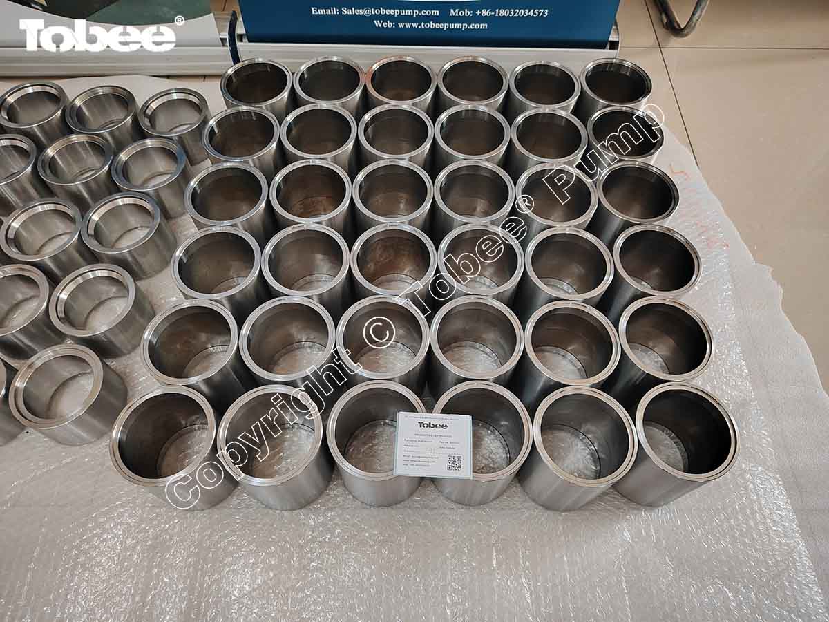
The shaft transfers rotational power from the motor or engine to the impeller. Motor speed, commonly 1450 rpm or 2900 rpm for 50 Hz supply and 1750 rpm or 3500 rpm for 60 Hz supply, directly sets pump performance, since head varies with the square of speed and flow varies linearly with speed for a given impeller. |
 |
 |
Mechanical Seal and Bearings
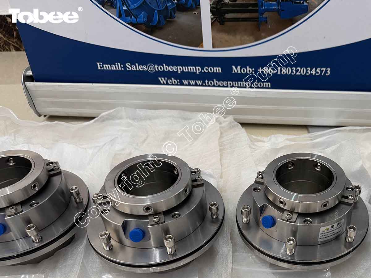
The mechanical seal keeps process fluid from leaking along the shaft, while bearings support the shaft and keep it running true. Seal face materials such as silicon carbide or tungsten carbide are chosen based on the abrasiveness and temperature of the pumped fluid, and bearing life is usually rated in the tens of thousands of running hours under correct lubrication.
|
Fluid enters through the suction connection, sized to keep inlet velocity low enough to avoid excess friction loss and cavitation risk, and leaves through the discharge connection, which is normally smaller in diameter than the suction port because the fluid is now under pressure.
|
Request a Quote |
The working cycle of a centrifugal impeller pump is straightforward once you break it into four steps.
Fluid enters the casing through the suction side, drawn in by the low-pressure zone created at the eye of the rotating impeller.
The motor or drive system spins the impeller at operating speed, and the rotating vanes accelerate the fluid outward from the impeller eye toward the vane tips, building kinetic energy.
As the fast-moving fluid leaves the impeller, it enters the expanding volute or diffuser passage in the casing. This expanding geometry slows the fluid down, and by the basic physics of energy conservation, that lost velocity reappears as increased pressure, or head.
The now-pressurized fluid exits through the discharge connection and continues into the downstream piping system.
This is the centrifugal impeller working principle in a nutshell, and it explains two practical facts every buyer should know. First, impeller diameter and rotational speed are the two variables that most directly set flow and head for a given pump casing, which is why manufacturers publish a family of performance curves for the same casing fitted with different impeller diameters. Second, because head generation depends on centrifugal force, a centrifugal pump impeller must be primed, meaning the casing needs to be filled with liquid before startup, or it will simply spin without building pressure — one of the few genuine disadvantages compared with a flexible rubber impeller pump, which offers limited dry self-priming ability at start-up.
Not every impeller looks the same, and the differences are not cosmetic. Impeller types are classified mainly by how enclosed the vanes are and by the material used to build them. Getting this choice right is probably the single most consequential decision in an impeller pump specification.
An open impeller has vanes attached to a central hub with no front or back shroud covering them. This exposed construction makes an open impeller the natural choice for fluids carrying suspended solids, stringy material, or moderate debris, because there is no shroud gap for particles to lodge in and clog. The trade-off is a slightly lower hydraulic efficiency compared with a closed design, typically several points lower at the same duty point, since some fluid recirculates around the vane tips. Open impellers are common in sump pumps, sewage pumps, and general dirty-water transfer duty.
A semi-open impeller has a shroud on one side only, usually the back side, while the front remains open. This design strikes a practical balance: it recovers some of the efficiency lost in a fully open design while still tolerating moderate solids and fibrous content. Semi-open impellers are frequently specified for wastewater, light slurry, and general industrial transfer where clean-water efficiency is desirable but a fully closed impeller would be too clog-prone.
 |
 |
A closed impeller has shrouds on both the front and back of the vanes, fully enclosing the flow passages. This construction delivers the highest hydraulic efficiency of the three designs, often in the 65 to 85 percent range for well-designed end suction centrifugal pump models on clean-water duty, because the enclosed passages minimize internal recirculation losses. The limitation is equally clear: closed impellers are prone to clogging when solids or fibrous material are present, so they are reserved for clean or lightly contaminated fluids such as potable water, cooling water, and clean process liquids.
A vortex impeller is recessed well back into the casing, out of the direct flow path. Instead of the fluid passing directly through the impeller, the rotating impeller creates a vortex, or swirling motion, in the casing that carries the fluid — including large solids, rags, and fibrous debris — around and out through the discharge with minimal direct impeller contact. This reduced contact lowers clogging risk dramatically and reduces wear on the impeller itself, though at a meaningful efficiency penalty, commonly in the 35 to 50 percent range. A vortex impeller pump is the standard choice for raw sewage, wastewater with rags and solids, and other genuinely dirty-water duties where reliability matters more than peak efficiency.
A rubber impeller pump uses flexible vanes, typically molded from nitrile, neoprene, or EPDM rubber compounds, that bend as they pass a cam or offset section of the casing and then spring back, creating a positive-displacement-like pumping action. This flexible geometry gives excellent self-priming behavior at low speed and gentle handling of the fluid, which makes rubber impellers popular for marine bilge and deck-wash pumps, light transfer duty, and applications where abrasion resistance to fine grit and flexibility under intermittent dry running are valued. Nitrile rubber typically tolerates continuous service up to roughly 65 to 80 degrees Celsius, so rubber impellers are not the right choice for hot water duty.

A stainless steel impeller, commonly cast from grades such as CF8M (equivalent to 316 stainless) or duplex stainless such as CD4MCu, resists corrosion from mildly to moderately aggressive chemicals, saline water, and food-grade fluids far better than standard cast iron. Stainless steel impellers are the default in food and beverage processing, pharmaceutical transfer, seawater handling, and chemical processing where product purity or corrosion resistance rules out cast iron. Compared with cast iron, stainless steel is preferable whenever the fluid is corrosive, needs to remain free of iron contamination, or must meet hygienic design standards, even though the material cost is noticeably higher.
| Impeller Type | Typical Efficiency Range | Solids Handling | Common Duty |
|---|---|---|---|
| Closed | 65% to 85% | Poor to none | Clean water, cooling water |
| Semi-open | 55% to 75% | Moderate | Wastewater, light slurry |
| Open | 45% to 65% | Good | Sump, sewage, dirty water |
| Vortex | 35% to 50% | Very good, large solids and rags | Raw sewage, fibrous solids |
| Rubber (flexible vane) | Positive-displacement action, low pressure duty | Fine grit, gentle handling | Marine, bilge, light transfer |
Efficiency figures above are representative ranges seen across common industrial centrifugal pump impeller types and vary by manufacturer, pump size, and specific speed. Always confirm actual performance against the manufacturer published pump curve for a given model.
Clean-water transfer, industrial water circulation, and general water pumping remain the largest single application category for the impeller pump, typically served by closed or semi-open water pump impeller designs running on end suction centrifugal pump platforms for straightforward, efficient duty.
Wastewater treatment plants, municipal sumps and pumps stations, and sewage and drainage systems depend on open, semi-open, or vortex impellers depending on how much rag, grit, and solids content is expected. Impeller selection matters enormously here, because a closed impeller chosen for efficiency alone will clog within hours on raw sewage duty.
Mud and slurry pumping, abrasive tailings transfer, and dredging and sediment removal call for open, semi-open, vortex, or purpose-built heavy-duty impellers, frequently cast in high-chrome white iron for maximum abrasion resistance. This is also the territory of what field crews often call a mud sucker pump — a heavy-duty, solids-handling unit designed to move thick mud and sediment without stalling or excessive wear.
Corrosive or chemically aggressive liquids demand careful material compatibility review, with stainless steel, duplex stainless, or fluoropolymer-lined wetted parts specified according to the chemical concentration, temperature, and pH involved.
Hygienic pump designs built with stainless steel impellers and easy-to-clean casing geometry support cleaning-in-place and sanitation requirements common across dairy, brewing, and beverage production lines.
A single impeller pump for hot water service needs seal materials, gasket materials, and impeller alloys rated for the actual operating temperature, since a standard nitrile rubber impeller or a standard elastomer seal will degrade well before an all-metal centrifugal pump impeller reaches its limit. Hot water and thermal-fluid circulation duty commonly calls for a hydraulic centrifugal pump fitted with a mechanical seal rated above 100 degrees Celsius and a cast iron or stainless steel impeller rather than a rubber impeller.
|
Contact Tobee Engineer Now |
Rather than making broad claims, it is worth being specific about what an impeller pump actually delivers in practice: continuous, non-pulsating fluid transfer, a wide range of achievable flow and head combinations across the centrifugal pump impeller types, a genuinely simple operating principle with few moving parts, multiple impeller designs available to match almost any fluid condition, a broad choice of impeller and casing materials from cast iron through stainless steel to rubber, suitability across most industrial applications from clean water to heavy slurry, straightforward integration with standard electric motors, and availability in both single impeller pump and multi-stage configurations where higher head is needed than one stage alone can provide.
Impeller diameter is one of the more technical, but genuinely useful, specifications to understand. It is simply the outside diameter of the rotating impeller, measured at the vane tips, and it is one of the two main variables — alongside rotational speed — that a manufacturer varies to fit one pump casing to a whole family of duty points.
The relationship follows well-established pump affinity laws: for a fixed casing and speed, head varies approximately with the square of impeller diameter, while flow varies roughly in direct proportion to diameter. Increasing diameter therefore raises head faster than it raises flow, and increasing diameter also raises the power draw on the motor, again related to the diameter ratio, so a diameter change on an existing installation should always be checked against the connected motor rated power.
Many end suction centrifugal pump casings are supplied with a range of trim diameters — for example a casing rated for a maximum 260 mm impeller might also be offered trimmed to 240 mm or 220 mm — allowing the same casting to cover several duty points on one published pump curve. Impeller trimming, where a supplier machines down the outer diameter of a standard impeller, is a recognized way to fine-tune performance to an exact operating point without moving to an entirely different pump size.
Before trimming or upsizing an impeller diameter, always check the manufacturer published pump curve rather than assuming a linear relationship holds perfectly, since real impeller geometry, vane exit angle, and casing volute design all affect the actual curve shape. It is also worth remembering that a larger impeller is not automatically better: oversizing a centrifugal pump impeller for the actual system head will push the pump into an overcapacity condition, driving up power consumption, accelerating wear, and increasing the risk of cavitation on the suction side.
Choosing the right impeller is not a single decision but the sum of several practical checks. Working through them in order tends to prevent the two most common and costly mistakes: undersizing for solids content, and oversizing for hydraulic duty.
Start with what you are actually pumping — clean water, wastewater, slurry, mud, aggressive chemicals, or high-viscosity fluids — since this single factor eliminates most of the wrong options before you even look at a curve.
Quantify suspended solids concentration by weight, note the maximum particle size expected, and be honest about clogging risk from fibrous or stringy material. A pump rated for 10 percent solids by weight and 25 mm maximum particle size behaves very differently under a slurry stream running 40 percent solids with 50 mm particles.
Determine your actual required operating point in cubic meters per hour and meters of head, then use the manufacturer pump curve to find where that point sits relative to the pump best efficiency point, rather than simply matching pipe size to pump size.
Confirm normal and maximum operating temperature, since this drives both seal material choice and impeller material choice — a nitrile rubber impeller pump is simply the wrong tool above roughly 80 degrees Celsius.
Cast iron remains the economical default for water and mildly abrasive slurry duty; stainless steel covers corrosive and hygienic applications; rubber-lined casings or a rubber impeller suit fine abrasive grit at moderate temperature; and specialized alloys such as high-chrome white iron or duplex stainless cover the more demanding abrasion and corrosion combinations.
These are two different failure mechanisms and deserve separate consideration. Abrasive wear comes from hard particles physically eroding the impeller and casing surfaces, while corrosion comes from chemical attack on the metal itself. A fluid can be abrasive without being corrosive, corrosive without being abrasive, or both at once, and impeller material should be matched to whichever mechanisms are actually present.
Higher rotational speed increases both flow and head from a given impeller, but it also increases wear rate on abrasive duty roughly with the cube of surface velocity at the vane tips, so slurry and mud sucker pump applications are frequently run deliberately slower than their clean-water counterparts to extend impeller and liner life.
An impeller pump and a gear pump solve the same basic problem — moving fluid — through fundamentally different mechanisms, so the right comparison is about matching mechanism to application rather than declaring one type universally superior.
| Factor | Impeller Pump | Gear Pump |
|---|---|---|
| Pumping principle | Dynamic, centrifugal or vane-driven | Positive displacement |
| Typical fluids | Water, wastewater, slurry, industrial fluids | Oils and viscous liquids |
| Flow characteristics | High-flow applications are common | Controlled, near-constant displacement per revolution |
| Solids handling | Depends on impeller design | Generally sensitive to hard solids |
| Viscosity | Best suited to low to moderate viscosity fluids | Often suitable for higher-viscosity fluids |
| Maintenance | Depends on wear pattern and application | Depends on gear, seal, and fluid condition |
The practical takeaway is that pump selection should always be based on your fluid, required flow, required head, viscosity, solids content, temperature, and overall operating conditions, rather than on pump type alone. For most water, wastewater, and slurry duty, an impeller pump is the natural fit; for high-viscosity oils and precise metering duty, a gear pump usually wins instead.
Favor open, semi-open, or vortex impellers based on solids concentration, particle size, and rag content, and prioritize clogging resistance and abrasion life over peak hydraulic efficiency.
Prioritize material compatibility and corrosion resistance first, then confirm temperature rating and seal compatibility with the process chemistry before finalizing impeller material.
Specify stainless steel construction, hygienic casing and impeller geometry with no dead zones, and confirm the pump supports your required cleaning and sanitation protocol.
Closed impellers are usually the right call for clean-fluid applications, since they deliver the strongest flow and head performance per unit of energy consumed, meaningfully lowering operating cost over the life of the pump.
A short, consistent maintenance routine keeps most impeller pumps running well past their expected service interval. Inspect impeller condition for wear, pitting, or imbalance; check bearing condition and lubrication; inspect mechanical seals for leakage or face wear; verify motor and electrical connections are tight and free of corrosion; monitor vibration and noise levels against baseline readings; check suction and discharge pressure against the expected operating point; inspect for external leakage at gaskets and seals; and remove accumulated solids from the casing and suction strainer where applicable.
|
Free Quote |
Possible causes include an incorrectly sized impeller for the actual system curve, a blocked or restricted suction line, a worn impeller that has lost vane profile and clearance, incorrect pump rotation direction, or the pump simply operating outside its designed flow and head range.
Possible causes include impeller imbalance, worn or damaged bearings, shaft misalignment between pump and motor, cavitation at the suction side, or foreign material lodged inside the pump casing.
Driven by abrasive solids content, corrosive fluid chemistry, excessive operating speed relative to the duty, or simply an incorrect material selection for the actual service conditions.
Usually traced to oversized solids relative to impeller passage size, an impeller configuration not suited to the solids content present, or genuinely insufficient solids-handling capability for the application, such as fitting a closed impeller where a vortex impeller was needed.
Cavitation shows up as a rattling or gravel-like noise, a drop in flow and head, and accelerated impeller pitting near the vane inlet edges. It is directly tied to suction conditions — specifically net positive suction head, or NPSH — and keeping the available NPSH comfortably above the pump required NPSH at the actual operating point is one of the most important design checks in any centrifugal pump impeller installation.
The impeller is the rotating component that transfers mechanical energy from the motor into kinetic energy in the fluid, which the pump casing then converts into usable pressure or head.
The main impeller types are open, semi-open, closed, and vortex designs, distinguished mainly by how much of the vane structure is enclosed by shrouds and by how directly the fluid contacts the rotating impeller.
An open impeller has no shrouds covering the vanes, giving it better solids tolerance but lower hydraulic efficiency, while a closed impeller fully encloses the vane passages between two shrouds, giving higher efficiency on clean fluids but poor tolerance for solids and fibrous material.
There is no single answer independent of your actual conditions — selection depends on solids content, expected particle size, required flow and head, and clogging risk, with open, semi-open, or vortex impellers each fitting different combinations of those factors.
A centrifugal pump impeller is the rotating vaned component inside a centrifugal pump that uses centrifugal force to accelerate fluid outward from its center, generating the flow and pressure the pump delivers.
Material selection depends on the abrasion level, corrosion potential, and temperature of the fluid, alongside general fluid characteristics — cast iron for general duty, stainless steel for corrosive or hygienic service, high-chrome iron for abrasive slurry, and rubber for gentle, low-temperature transfer.
Service life depends heavily on fluid conditions, the actual operating point relative to the pump best efficiency point, impeller material, and how consistently the maintenance routine is followed, so published life figures should always be treated as a starting reference rather than a guarantee.
Yes, in most industrial pumps the impeller is a replaceable wear part, and replacement is practical as long as the new impeller matches the original pump specifications for diameter, material, and vane geometry, since a mismatched replacement can shift the entire performance curve.
Tobee Pump designs and manufactures industrial impeller pumps for water, wastewater, slurry, and heavy-duty solids-handling applications, with a product range built around submersible pumps, slurry pumps, sewage and wastewater pumps, dredging pumps, and drainage pumps. Every pump leaves the factory with impeller configuration, impeller material, discharge size, motor power, flow, and head selected to match the actual project requirements rather than a generic catalog default.
Whether you need an open impeller for a sump station, a vortex impeller pump for raw sewage duty, a high-chrome slurry impeller for mud and sediment transfer, or a stainless steel impeller for a corrosive process line, the Tobee Pump engineering team can confirm the right impeller type, material, and pump curve for your operating point before you place an order.
If you are specifying an impeller pump for water transfer, wastewater, slurry, mud, or a hot water application, our team can review your fluid data, required flow and head, and solids content, then recommend the correct impeller type and material for your operating conditions. Reach out through our contact page, or browse our slurry pump and submersible pump product categories to see current models and technical drawings.
 Sara Liang
 +86 189 3110 6396 (Whatsapp/Wechat)
 Inquiry@tobeepump.com
The impeller is the single component that decides how an impeller pump performs, and understanding it changes how you read a pump datasheet. Open, semi-open, closed, and vortex impellers each bring a different balance of efficiency and solids tolerance, while rubber and stainless steel impellers extend the range further to cover gentle low-temperature transfer on one end and corrosive or hygienic service on the other.
Correct selection should weigh flow, head, solids content, particle size, viscosity, temperature, corrosion potential, and abrasion resistance together, rather than defaulting to whatever impeller type was used on the last project. Once the right impeller is in place, a consistent maintenance routine — checking impeller condition, bearings, seals, and suction conditions on a regular schedule — does most of the remaining work to prevent wear, clogging, vibration, and unplanned downtime.
If you are working through a real selection decision right now, get in touch with Tobee Pump. Send us your fluid characteristics, required flow and head, solids content, and operating temperature, and we will help you match the correct impeller pump to your actual conditions rather than a generic specification.
• How to Choose the Right Sand Pump for Grit Handling Applications
• How to Select the Best Sump Pump for Mining, Construction, and Dewatering
• How to Choose the Right Gravel Pump for Heavy-Duty Applications
• Understanding Slurry Pumps: Working Principles, Pump Types, and Care Guide
• The Complete Guide to Submersible Pumps: Everything You Should Know
• How Does a Self-Priming Pump Work? Types, Advantages, and Industrial Applications
• Industrial Pumps Guide: Types, Applications, and Selection Tips
• Cement Slurry Pump for Aggregate Plants: Applications and Selection Guide
• Centrifugal Pump Parts: Complete Guide to Components, Functions, and Materials


